
Lander Flight System Description
Cruise Stage
Redundant star cameras, sun sensors Two solar arrays: 2.6 m2 total area X-Band transmit/receive horn (Medium Gain Antenna) MGA,
1 patch LGA (Low Gain Antenna),
redundant pair of solid state power amplifiers (SSPA's)3 axis control: redundant IMU's, 4 reaction engine modules (REM's) located on Lander Each REM contains 1 aft-facing 5-lbf TCM thruster
and 1 1-lbf RCS thruster [canted outward 20

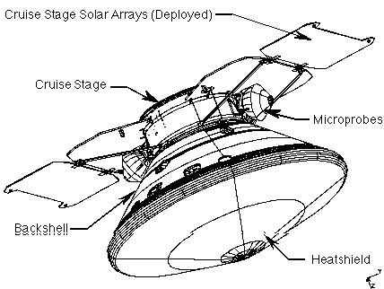
1998 Mars Surveyor Lander Cruise Configuration
The lander flight system consists of a separable cruise stage with a MDAC V-band launch vehicle separation interface, and propulsive lander/entry assembly. The cruise stage is jettisoned just prior to atmospheric entry, providing a clean aerodynamic shape for entry and a reduced ballistic coefficient. Cruise stage operational components include redundant star cameras and sun sensors for attitude determination, two solar array wings (2.6-m2 total area) for power generation, an X-Band medium gain transmit/receive horn antenna and one low gain receive patch antenna and a redundant pair of solid state power amplifiers (SSPA's) for telecommunications during cruise. Three-axis attitude control during cruise is provided using a redundant Inertial Measurement Units (IMU's) and four cruise reaction engine modules (REM's) located on the Lander. Each REM contains one aft-facing 5-lbf TCM thruster and one canted (20 degrees out, 15 degrees aft) 1-lbf RCS thruster.
Entry, Descent and Landing (EDL) System
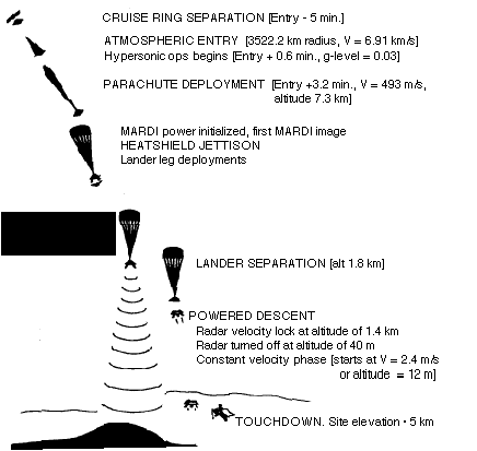
2.4 meter heatshield (ablator) based on Mars Pathfinder design Ballistic coefficient 58 - 62 kg/m2 , PF parachute design Mortar parachute deployment based on IMU velocity estimate Heatshield separates after parachute deployment,
landing legs are deployed, descent engines are warmed with short pulsesMARDI starts operating just prior to heatshield separation Flight software attitude control algorithms determine optimum time for
lander release & start of powered descent phase

The EDL System
The 2.4 m diameter heatshield structure and ablator makes use of the tooling developed for Pathfinder, sharing the same nose radius and cone angle. The ballistic coefficient is 58 to 62 kg/m2, somewhat lower than Pathfinder. The Pathfinder parachute design is used to lower cost. As on Pathfinder, the parachute is deployed based on an on-board navigator velocity estimate, eliminating the long-range radar altimeter used on Viking. The parachute is mortar-deployed to ensure good separation for inflation in the freestream. After parachute deployment the heatshield is separated from the backshell, 3 landing legs are deployed, and the descent engines are warmed with short firing pulses. The MARDI descent imager starts operating shortly before heatshield separation. After a short parachute ride the flight software attitude control algorithms determine the optimum time to release the lander from the backshell/parachute to begin the powered descent phase.
Propulsion System
2 diaphragm tanks (64 kg total hydrazine capacity) used
for translational and rotation ÆV for all mission phases.Pressure regulated with He pressurant Final Descent:
- Doppler radar provides altitude & velocity estimates
- Twelve pulse modulated 266 N engines, 3 groups of 4 engines each
- 2.4 m/s constant vel terminal descent phase starts 12 meters above surface
- Engines cut off when any of the footpads touch the surface
- AACS subsystem controls landed orientation to place X axis within
5 degrees of desired azimuth (45 degrees West of North)Two diaphragm propellant tanks contain the 64 kg of purified hydrazine propellant used for both cruise maneuvers and attitude control as well as for lander powered descent. This is a pressure-regulated system with serially-redundant pressure regulators utilizing helium gas pressurant. For final descent, a Doppler radar provides accurate altitude and 3-D velocity estimates. Descent control is provided by twelve 266 N retro-engines arranged in three groups of four engines each. The engines are pulse modulated. As the lander descends to within 12 meters of the surface the spacecraft control system begins the 2.4 m/s constant velocity terminal descent phase. Landing engines are cutoff when any one of the lander footpads touches the planet surface. The AACS subsystem controls the orientation of the lander on landing, placing the X axis within 5 degrees of the desired azimuth (45 degrees West of North, to maximize the solar array efficiency and minimize Direct To Earth (DTE) antenna blockage).
Structure
Composite: honeycomb Aluminum core with graphite-epoxy facesheets Legs: spring-deployed, Aluminum, with crushable inserts Thermally isolated component deck inside central thermal
enclosure, contains C&DH, PDDU, CCU, Ni-H common
pressure vessel batteries, telecom (X-band direct and UHF relay), heat pipeExternally mounted componenets used during EDL are:
gyros, pyro firing electronics, radarThe Lander structure is constructed of a composite material consisting of honeycomb aluminum core with graphite-epoxy facesheets bonded to each side. A thin aluminum sheet is bonded to the composite to provide a Faraday cage around the thermal enclosure. The landing legs are made of aluminum and have compression springs to deploy the legs from the stowed position. Tapered, crushable, aluminum honeycomb inserts in each leg provide the shock absorption necessary for landing. The design has a thermally isolated component deck inside of a central thermal enclosure to control the thermal environment for spacecraft and Payload electronics. Located within this enclosure is the Command and Data Handling (C&DH) electronics, the Power Distribution electronics (PDDU), the Charge Control Unit (CCU), the Nickel-Hydrogen Common Pressure Vessel Batteries (CPV's), The X-Band and UHF telecommunication electronics, and the Capillary Pump Loop Heat Pipe (LHP) components. Imbedded within the component deck are the LHP evaporators which transfer heat from the aluminum facesheets of the component deck to the LHP radiators located outside of the thermal enclosure. Components used only during EDL are mounted external to the enclosure to maximize volume inside the thermal enclosure for on-surface functions (The gyroscopes, pyro firing electronics, radar and radar electronics are located outside the thermal enclosure).
Power and Thermal
6 Solar panels (4 fixed, 2 deployed) provide power during
"daytime" - defined to be when sun is above 10 degrees elevation.Batteries (16 A-hr) provide night-time heater power for thermal enclosure C&DH and Power distribution electronics have low-power night-time sleep mode Payload allocated 25 Watts continuous when operating Spacecraft daytime operations ~ 8-9 hrs (landing), decreases towards the end of the mission Designed for full operation in atmosphere up to opacity of 0.5.
Operation during dust storm TBD.Mission ends when batteries freeze For the landing footprint of 75° to 78° South latitudes the sun does not go below the nominal horizon for the season of the prime mission. However, a 10° terrain mask is assumed for power analyses and results in a defined day and night interval when the sun goes below the horizon mask. The solar array, consisting of 6 panels (4 fixed, 2 deloyed) provides power during the daytime for payload operations and recharges the batteries which provide nighttime heater power for the thermal enclosure. The C&DH and Power Distribution electronics have a low-power sleep mode to reduce energy consumption at night. The lander lifetime is limited by the size of the batteries. As the nights get longer and colder late in the summer the heater power required at night increases until the demand can no longer be satisfied by the 16 A-hr batteries. The batteries then freeze and the mission ends. Daytime operations are limited by the size of the arrays and the amount of power required to recharge the batteries. The duration of the payload and spacecraft daytime operations is approximately 8-9 hours at landing, but decreases as the sun goes lower in the sky. The power system is designed for full operation in a dusty atmosphere of opacity (Tau) = 0.5. Survival under full dust storm conditions (Tau = 1) TBD may be possible with advance planning but is not a design requirement.
Telecommunications
Primary link for data relay & commanding is the UHF link to the Mars Surveyor 98 orbiter,
downlink via Mars Global Surveyor also available8 - 10 UHF passes above 20 degrees terrain mask available for each orbiter per day X-band DTE with steerable dish available as command/relay backup.
1 hr duration supported by thermal limitsNumber of UHF and DTE cycles per day limited by daytime power The primary telecom link for science data relay and spacecraft commanding is the UHF relay link to the '98 orbiter. A UHF link to Mars Global Surveyor is also available, for data relay only. Eight to ten UHF communication passes above 20° effective terrain mask can occur with each orbiter each day. An X-band, Direct-To-Earth link with a steerable dish is provided as a transmit/receive backup. The maximum duration of an X-Band transmit event is limited to one hour by the capability of the Loop Heat Pipe to transfer the heat energy from the X-Band Solid State Amplifier out of the thermal enclosure. The number of UHF and X-Band use cycles is limited by the amount of daytime power available.
| Home | Mars Polar Lander | Deep Space 2 Microprobes | Mars Climate Orbiter |
| Welcome | Mailing List | Links | Credits |
For questions or comments on this website please refer to our list of contacts.